
PeterCade: Mame table-top arcade cabinet


 It's been said that every self-respecting geek should build a
MAME
arcade cabinet
in his/her lifetime. Well, mine is PeterCade.
It's been said that every self-respecting geek should build a
MAME
arcade cabinet
in his/her lifetime. Well, mine is PeterCade.
This sounds like a daunting job, but, nowadays, an arcade cabinet is essentially a PC in a wooden case. Quite unlike the cabinets made by the first hobbyists in the nineties; they had to make them from real commercial cabinets' components. Which meant you had to know a lot about how these cabinets were built.
Also, thousands have gone before me so I have

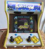
Pictures of the finished article


Design
I have based the design of PeterCade on the Weecade. This is a very popular table top model and you will find many people who have built a Weecade clone. I didn't stick to all measurements precisely and have deviated here and there. For example, I didn't dare to put the internal moldings in before assembling the basic structure.Special features
| Power socket | Not sure if it's that special but I wanted a power socket at the back to plug in a normal computer cable |
| Audio controls | Although you can control audio (like volume) using hot-keys in software, nothing beats real audio control buttons. I have bought an audio amplifier with buttons that can be mounted at the back of the cabinet |
| USB ports | In order to easily hook up keyboard, mouse, USB sticks etc I wanted some USB ports at the back. I have bought a SilverStone FP32, removed the metal casing and mounted the i/o panel at the back. |
| Back-panel hatch | For easy access I have built the back panel in two parts. The bottom part is fixed and has the power-outlet, audio controls and USB ports. The other part is hinged sothat I can open the cabinet |
| T-molding | I felt PeterCade wasn't complete without a nice piece of T-molding |
Components
Buying components for an arcade is actually not very complicated as most are readily available. More tricky are the control panel parts (buttons, joystick etc). The UK has a few dedicated (online) arcade shops and in the Netherlands I can wholeheartedly recommend the ArcadeWinkel.Audio
| Amplifier | 12V amplifier with audio control buttons |
| AC adapter | Generic 12V 300mA power adapter |
| Speakers | Visaton F8SC 2x20 Watt car speakers |
| PCB feet | PCB feet (x4) |
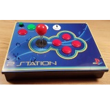
Control panel
| Joystick | Mag-Stik Plus (black, 2x) |
| Push buttons | Convex classic buttons (yellow, 8x) and for escape and pause (blue, 2x) |
| Push buttons | Front panel mounted buttons with built-in microswitch for coin, 1P and 2P |
| Extra buttons | Top-monuted buttons for service and power (green 2x) |
| Decals | Coin, 1P and 2P decals for the white front-buttons (bought from a guy in the US) |
| Controller | Xin-Mo mini 2-player controller with cableset |
Standard computer components
| Monitor | Generic Acer 17" LCD monitor |
| Motherboard | Asrock E350M1 (built-in AMD Dual-Core Processor E350/E350D), with 2GB RAM |
| SDD | Kingston SSDNow V300 60 GB |
| Silent PSU | Pico picoPSU-90 + 80 Watt Adapter | I/O back-panel | SilverStone FP32 , 4 USB2 ports, audio ports and firewire |
Electrical
| Marquee lights | 12V LED-strip |
| Power switch | Power switch with EMI filter |
| Power cable splitter | Double computer cable (Schuko to 2x C13) |
| Wire connectors | 3 WAGO 222 connectors |
Miscellaneous
| T-molding | 19mm T-molding (yellow, 2 meter) |
| T-molding router bit | Router bit |
| Plexiglas | Generic 2mm Plexiglas for marquee, control panel and monitor protection. This Dutch company cut all three to size, drilled the screw holes, joystick & button holes and painted the artwork on the marquee & control panel. They did an excellent job! |
Pictures of components


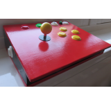
Building
The basic steps in building PeterCade:- Cut the various panels to size. The side panels are 18mm, all others 8mm
- Drill holes
- Button holes in the front panel (for coin, 1P and 2P buttons)
- Button holes for small service button and power button in the top panel
- Holes for the speakers in the speaker panel
- Holes in the lower part of the backpanel for power switch, audio control buttons and the i/O panel
- Holes in the hinged-part of the backpanel for ventilation
- Route the groove in the side panels for the T-molding
- Build the basic structure including the monitor bar, excluding the back-panel hinged part and the control panel
- Paint: 2 layers of primer and 2 coats of paint
- Fit speakers in speaker bar (using screws)
- Fit back-panel components: power switch (screws), amplifier (using PCB feet) and io/panel (using custom made wooden frame, screwed to the back-panel)
- Fit pc components: motherboard (using stand-off screws), PSU adapter block (double-sided velcro tape) and SDD (double-sided velcro tape)
- Hook up speakers: standard audio cable from motherboard to amplifier and standard speaker cables from the amplifier to the speakers (using blade connectors (aka cable shoes))
- Wiring: see wiring section below
- Mount monitor unto monitor bar
- Paint the monitor Plexiglas (2 layers of special primer and then 2 coats of paint) and screw to the cabinet
- Make the control panel, wire all buttons (including the front & top panel buttons) and screw to the cabinet
- Fit hinged-back panel
- Fit T-molding. I glued mine using 2-part epoxy glue with moderate success. The groove is a bit too wide for the T-molding. The glue doesn't so much fix the T-molding in place but rather fills the groove making the fit a bit tighter
Image gallery of the build phase


Control panel
The control panel is made of a piece of 450mm x 198mm x 8mm MDF and a 2mm sheet of Plexiglas. This Dutch company cut the plexi to size, printed the artwork (at the back!) and drilled the joystick, button and screw holes for me. I provided them with a transparent .PNG of my artwork. The machine-cut holes in the Plexiglas fitted perfectly with the artwork; a beautiful job.I drilled the joystick and button holes in the MDF myself and for whatever reason I couldn't get the holes lined up correctly with those of the Plexiglas. I ended up having to make some of the holes in the MDF a bit bigger, which, fortunately, can't be seen from the top because the buttons and the joystick fully cover the gaps.
The joystick is screwed directly on top of the MDF, so I can't easily replace it. The alternative was to have screw holes drilled in the Plexiglas but then there would be 8 extra screw heads visible. And the risk of cutting your hand against them during gameplay. I prefer the current solution - is looks much neater.
The beauty of these Mag-Stik Plus joysticks is that they dynamically can be set to 4-way or 8-way play, although it is a bit of a fiddle. I have nothing but praise for these joysticks: very precise handling and they definitely look the part.
The front-buttons for coin and 1-player and 2-player I had bought initially didn't fit - they pushed against the joystick. I didn't have much choice because they were the only ones with printed coin, 1P and 2P signs. After finding a guy in the US who could print these decals for me, I bought new white buttons; they have their microswitch built in and are therefore not so high. Fortunately these buttons didn't clash with the position of the joysticks.
The wiring at the back of the control panel is relatively straight forward. The joystick has 4 microswitches and every button has 1. They are all connected to an Xin-mo 2-player controller. The one I bought already came with a cableset. There is one huge so called ground-train cable which connects the ground pin on the controller with one pin from each button & joystick's microswitch. Then the other pin on each button & joystick's microswitch is connected to the according pin on the controller. The 3 buttons at the front and the 2 small buttons on the top of cabinet also connect to the controller. I'm not very good at tidy wiring so it is a bit of a mess. Probably a good thing I don't have a picture of it :-)
The controller has a USB-B connector which you connect with a standard USB cable to a PC or, in this case, directly to the motherboard. It presents itself as a USB joystick controller.
Another interesting snippet is that I initially wanted to paint the MDF control panel dark brown and the cabinet side panels off-white. A similar color scheme as the Weecade. However, when I put the transparent Plexiglas on top of the brown MDF panel, the artwork could hardly been seen. So, I decided to swap colors: the control panel in white and only the side panels in dark brown. Looks much better, particularly with the yellow T-molding.
Control panel images


Wiring
This part has taken me longest to figure out. I wanted to mess about with power as little as possible. And I definitely didn't want to do any kind of soldering.Components that need power
| Motherboard PSU | A normal 90 Watt power block (like a laptop) which has a standard C13 computer cable socket |
| Monitor | Just like the PSU a C13 socket |
| Amplifier adapter | Standard Euro plug |
| Marquee LED lights | A 12V wire and a ground wire |
I have chosen to power the audio amplifier using a dedicated 12V adapter. The alternative was powering it from the motherboard using a 12V molex connector. I decided against the latter because the good people of arcadewinkel.nl advice against it - may cause static noise and humming.
The LED lights were the easiest to solve. I have connected one end of a molex connector to a molex plug on the motherboard, cut off the other end and used some blade connectors (aka cable shoes) to connect to the 2 LED wires. To be precise: the yellow molex wire (carrying 12V) and one of the 2 black molex ground wires.
The other 3 components are connected to the powerswitch. The cable splitter feeds the monitor and PSU. I have cut off its plug and connected the 3 wires directly to the powerswitch with blade connectors (aka cable shoes).
The 12V adapter for the amplifier has its electronics built into the plug (which I shouldn't cut off) so I have bought a Europlug extension cable. I have cut off the extension cable's plug and cut the cable splitter mid-way. The 3 cables (with 3 wires each) I have connected using 3 WAGO 222 connectors.
The monitor is mounted behind plexiglas and is permanently switched on. So as soon as power is applied to the power switch the monitor will turn on.
In general, motherboards need to be switched on via a power button. I have used a small service button mounted on top of the arcade to turn on the motherboard. I have used a 2-pin motherboard header cable, plugged one end onto the 2 power pins on the motherboard header, cut off the other end, fitted two blade connectors (aka cable shoes) to them and connected them to the button's microswitch pins. As can be seen in some of the images, during the built I had temporarily connected a blue button to the motherboard's powerswitch.
Artwork
Although terrible at anything artistic, I did make the artwork myself. Or better said, I stole bits and ideas from others. Here is a PNG of the control panel and a PDF of the marquee. If you want the originals (both in powerpoint no less :-)) email me.
And yes, I did make a mistake by printing Peter's Cade on the marquee; that should have been PeterCade.
Artwork pictures


Software
Apart from Windows XP, I've used MAME and MaLa (MAME front-end). I didn't really see the need to install other game emulators.Windows XP
The Windows XP configuration is all quite straight forward. Installing Windows XP & the motherboards drivers is the first step. Then I have tweaked Windows XP to get rid of the standard Windows UI from start until the MaLa frontend starts, see the table below. I have set the screen size to 800x600 pixels.
Windows XP configuration
| Custom splash screen | Follow these instructions on setting a custom splash screen . This is PeterCade's custom splash screen |
| Booting straight in front-end | You can change Windows Explorer with your own front end application |
| Removing startup dialogs | Get rid of start up dialogs |
MAME
I have used a custom built of MAME version 0.148. The only change I've made is disabling the warning startup screens which I find annoying. Other than configuring the joysticks & buttons there is nothing special you need to for MAME. If you are interested in running MAME then I assume you know what to do about game ROMS. Either way, don't contact me about where to find them - you are on your own there.
MaLa
After looking at alternatives I've settled on MaLa, version 1.74 for MAME's frontend.
Basic MaLa configuration
| Game lists | I have used ROMLister to create category-based gamelists (platform, driving, fighting, favorites etc) |
| PeterCade layout | Here are PeterCade's layout files (minor modifications to the ones used by nanocade). Unzip (with directory structure) in MaLa's root directory. Afterwards edit mala.ini and set SelectedLayout to petercade |
| MaLa configuration | I have spent quite some time to get the MaLa configuration right and know this can be a bit of a fiddle. In case it helps I provide all MaLa config files, which is a zip of my MaLa directory (minus the binaries). Config files are normal text files so you can study/copy or do whatever you want |
Extra MaLa configuration
| Marquee artwork |
I have stored them in the MAME directory structure and configured MaLa accordingly
(MAME Config->Pictures and Videos->Marquee Pic) |
| Snapshot files |
I have stored them in the MAME directory structure and configured MaLa accordingly
(MAME Config->Pictures and Videos->Snap / Title) |
| History info |
I have stored history.dat in the MAME root directory and configured MaLa accordingly
(MAME Config->Additional->history.dat file) |